LX Gas Spring Resource
Gas Spring Mounting Position Calculation: Geometry, Stroke and Force
Work out where to mount a gas spring: hinge, centre of gravity and pivot points, stroke and length, effective lever arm, force, and a full worked example.

Where you put the two ends of a gas spring decides almost everything about how a lid behaves: how much force you need, how far the spring has to travel, how far the lid opens, and whether it stays shut or pops open. This guide shows how to work out a gas spring mounting position from the hinge, the lid's centre of gravity and the two pivot points, with one complete worked example you can repeat with your own numbers.
Short answer: fix the hinge, the lid's centre of gravity and the open angle first. Then choose an upper pivot on the lid and a lower pivot on the frame. The distance between the pivots with the lid closed is the spring's installed compressed length; the distance with the lid open is its extended length; the difference is the stroke you use. The force per spring is F = m × 9.81 × d / (n × L), where L is the effective lever arm: the perpendicular distance from the hinge axis to the spring's centre line, measured with the lid closed. Finally, check that the spring still balances the lid at every angle, not only when closed.
The Points That Define the Geometry
Draw the lid from the side, with the hinge axis as a point. Four positions matter:
- Hinge (H): the pivot the lid turns about.
- Centre of gravity (CG): where the lid's weight acts. For a uniform lid it is at half the depth; handles, glass or locks move it. The horizontal distance from the hinge to the CG is d.
- Upper pivot (A): the gas spring mount on the lid, a distance a from the hinge along the lid.
- Lower pivot (B): the gas spring mount on the frame or side wall.
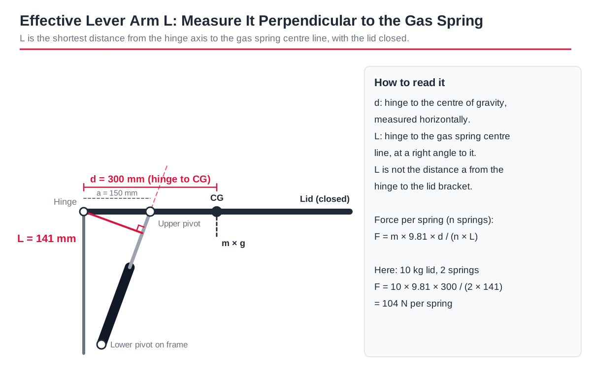
The effective lever arm L is not the bracket distance a. It is the shortest distance from the hinge to the line through A and B. With the hinge at (0, 0), A at (xA, yA) and B at (xB, yB), it is L = |xA × yB − yA × xB| / (pivot distance AB). The same definition is used in the gas spring force calculator.
Step 1: Fix the Hinge, Centre of Gravity and Open Angle
Measure the lid depth, weigh the lid, and find the CG. Decide the open angle the user needs, for example 80 to 90 degrees for a toolbox or service hatch so the lid clears the user's head and stays out of the way. Note anything that limits the spring: side walls, shelves, wiring, the latch and where hands go.
Step 2: Place the Two Pivots
Start with the upper pivot a short way along the lid; a quarter to a third of the lid depth is a common first try. A pivot closer to the hinge needs a shorter stroke but a much higher force; a pivot further out needs less force but a longer spring and more space.
Put the lower pivot on the frame below the hinge, so the spring's centre line stays on the same side of the hinge for the whole opening. If the line crosses the hinge, the spring changes from opening to closing the lid; that is only wanted in a deliberate over-centre design. Mount the spring rod-down where possible, so the seal stays lubricated (see the mounting guide).
Step 3: Spring Length and Stroke From the Pivots
Measure or calculate the distance between the two pivots in both positions:
- Pivot distance closed = the spring's installed length when the lid is shut. It must be a little longer than the spring's compressed length, so the spring is not bottomed out against the lid.
- Pivot distance open = the spring's length when the lid is open. If the spring is fully extended here, the spring itself sets the open stop.
- Stroke used = pivot distance open − pivot distance closed. The spring's stroke must be at least this long.
A gas spring's extended length is roughly twice its stroke plus the fixed length of the tube end, guide and end fittings, so a long stroke in a short space is not always possible. Check the lengths against the gas spring dimensions guide, measured centre to centre of the end fittings you will use.
Step 4: Effective Lever Arm and Force
With the lid closed, work out L as above and use F = m × 9.81 × d / (n × L) for n springs. Add a margin, often 10 to 15%, for hinge friction, seals and cold weather. If the force comes out very high, move the upper pivot further from the hinge or the lower pivot further from the lid line before reaching for a stronger spring.
Worked Example: 10 kg Toolbox Lid
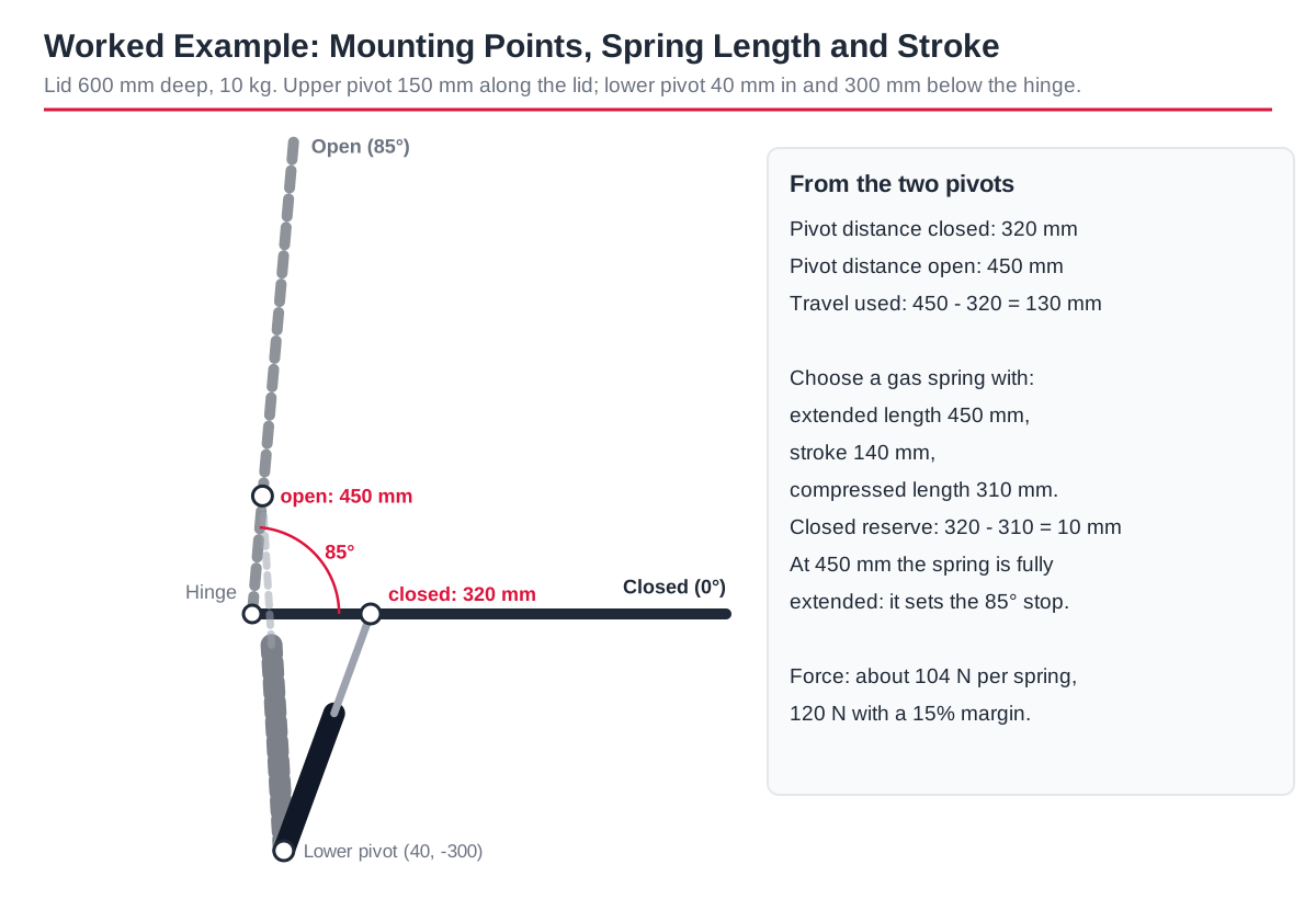
A lid is 600 mm deep and weighs 10 kg, so d = 300 mm. Two gas springs will be used, and the lid should open to 85 degrees. Coordinates are in millimetres with the hinge at (0, 0) and the closed lid along the x axis.
- Upper pivot A: 150 mm along the lid, at (150, 0) closed.
- Lower pivot B: on the side wall, 40 mm in and 300 mm below the hinge, at (40, −300).
- Pivot distance closed: √(110² + 300²) = 320 mm.
- Open at 85 degrees, A moves to (13, 149); pivot distance open = 450 mm.
- Stroke used: 450 − 320 = 130 mm.
- Effective lever arm closed: L = 150 × 300 / 320 = 141 mm.
- Force: F = 10 × 9.81 × 300 / (2 × 141) = 104 N per spring; with a 15% margin, about 120 N.
A spring with 450 mm extended length, 140 mm stroke and 310 mm compressed length fits: it leaves 10 mm of reserve when the lid is shut and is fully extended at 85 degrees, so it also acts as the open stop.
Step 5: Check the Balance Through the Whole Opening
The formula balances the lid only in the closed position. As the lid opens, the lid's moment falls with the cosine of the angle, while L also changes. Check a few angles; here with two springs at 120 N each:
| Lid angle | Pivot distance (mm) | L (mm) | Lid moment (N·m) | Spring moment (N·m) |
|---|---|---|---|---|
| 0° | 320 | 141 | 29.4 | 33.8 |
| 15° | 355 | 127 | 28.4 | 30.5 |
| 30° | 386 | 109 | 25.5 | 26.1 |
| 45° | 411 | 88 | 20.8 | 21.0 |
| 60° | 431 | 64 | 14.7 | 15.4 |
| 75° | 445 | 39 | 7.6 | 9.4 |
| 85° | 450 | 22 | 2.6 | 5.3 |
The spring moment stays above the lid moment at every angle, so the lid lifts on its own and holds at 85 degrees. Two things follow. First, the margin is thin around 30 to 45 degrees, so a heavier lid or a cold day could leave the lid hanging there; a real gas spring pushes harder when compressed, which helps near the closed end. Second, because the spring wins even when closed, this lid needs a latch. If the lid should stay shut under its own weight and only rise after a lift, move the lower pivot so the spring line passes closer to the hinge when closed (a smaller closed L), then repeat the check.
Vertical Lift: Gas Spring in Line With the Load
When the gas spring pushes straight up in line with the load, for example under a lift-up seat, platform or table top that moves vertically, there is no lever arm: F = m × 9.81 / n. A 30 kg top on two springs needs 30 × 9.81 / 2 = 147 N per spring before the margin. Check that the guides take any side load, because a gas spring should not act as a guide. If the top must stop at any height, use a lockable gas spring.
Common Mounting Mistakes
- Measuring L as the bracket distance along the lid instead of perpendicular to the spring.
- Checking only the closed position, then finding the lid hangs half open.
- Leaving no reserve, so the spring bottoms out when the lid is closed.
- Letting the spring line pass over the hinge, so it pulls the lid shut near closed.
- Mounting the spring at an angle across the lid, which adds side load to the rod and seal.
- Using brackets that flex, which changes the geometry under load.
Send Your Geometry for a Check
Send the hinge position, the two pivot coordinates (or a side-view drawing), lid weight and depth, centre of gravity, open angle and the end fittings you plan to use. An LX engineer can check force, stroke and lengths through the full opening before you order samples. Ask an engineer or estimate the force first with the force calculator.
Frequently Asked Questions
How do I calculate a gas spring mounting position?
Fix the hinge, centre of gravity and open angle, choose an upper pivot on the lid and a lower pivot on the frame, then calculate the pivot distance closed and open (spring lengths and stroke) and the effective lever arm (force). Check the balance at several angles and move a pivot if the lid does not behave as wanted.
Where should a gas spring be mounted on a lid?
A common starting point is a quarter to a third of the lid depth from the hinge, with the lower pivot below the hinge so the spring line never crosses it. Closer to the hinge means a shorter stroke but more force.
What length gas spring do I need?
The extended length equals the pivot distance with the lid open, and the compressed length must be a little shorter than the pivot distance with the lid closed. The stroke is at least the difference between the two.
How do I calculate a gas strut for vertical lift?
If the spring pushes in line with the load, divide the weight force by the number of springs: F = m × 9.81 / n, then add a margin. No lever arm is involved.
Why does my lid pop open, or not stay open?
If it pops open, the spring moment is larger than the lid moment when closed; add a latch, reduce the force, or move the lower pivot so the closed lever arm is smaller. If it will not stay open, the spring moment is too small near the open position; increase the force or move a pivot so the lever arm is larger there.